Even though the micro USB pin and micro USB B cables are going obsolete and is being replaced by latest and more advanced USB-C, the device with previous micro USB one are still in the circulation and more or less people tends to use them until they go unusable.
One common combination was from the USB Type-A to the micro USB Type-B. Another one is from the latest USB Type-c to the standard USB Type-A, all these are often found in phone chargers, rechargeable Bluetooth speakers and what not…
USB wiring diagram below are great for engineers and hobbyists who like to work with electronics DIY and circuits. So whether your USB port/ cable is out of order or you’re just curious about how things are wired, a given USB wiring diagram can be really useful!
USB cables can go bad when they’re bent too much on a regular basis, which damages the copper wires inside, even though copper is usually good for making wires and properly insulated to prevent core damage.
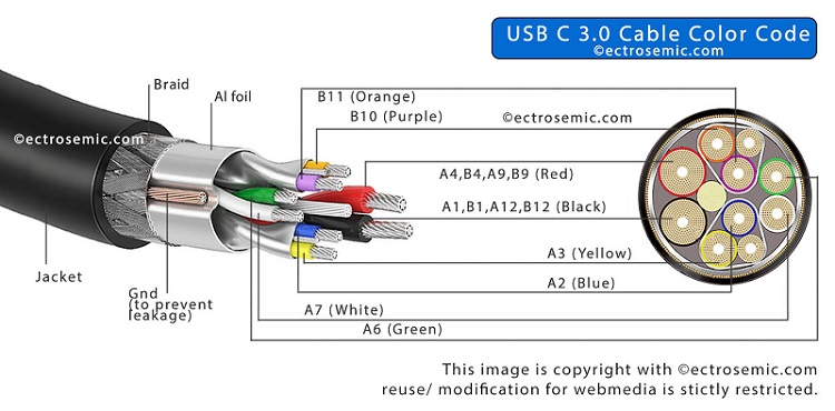
Check here new USB C color code
Table showing male USB-A pinout & USB-B pinout:
Pin No. | Name | Wire code | Description |
|---|---|---|---|
| 1 | VCC | Red/ Orange | +5V (dc power) |
| 2 | D- | White/ Gold | Data- (data from device to host) |
| 3 | D+ | Green | Data+ (data from host to device) |
| 4 | GND | Black/ Blue | 0V (dc ground) |
The table showing pin and their nomenclature along with its function in short.
- Pin no.1 showing the power line (+VDD) through that pin the power is delivered to the device or any which is also act as indicator of handshake signal, flags “the device is connected”.
- The power supply voltage is +5V for this cable and connector (it may be different for different USB-PD technology)
- Whereas, “pin no. 2” (D-) is used as a data reception pin, similarly “pin no. 3” (D+) is also used as a data transmission pin.
- The work of the D+ & D- pin is to send and receive the data in a according to USB protocol.
- Pin no. 4 is connected to ground.
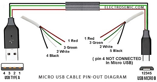
- The wire is color coded in the USB cable are Red, White, Green, Grey, black for pins 1, 2, 3, 4 and 5 respectively.
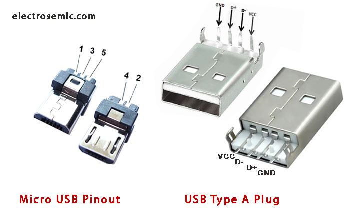
Table of mini and micro USB pin-out type-b & type-a:
Pin No. | Name | Wire code | Description |
|---|---|---|---|
| 1 | VCC | Red | +5V (dc power bus) |
| 2 | D- | White | Data- (device to host) |
| 3 | D+ | Green | Data+ (host to device) |
| 4 | ID | N/A (dark blue / black)* | ID (generally not connected, or grounded accodingly) |
| 5 | GND | Black | 0V (dc ground) |
The pin-out diagram for micro USB Type-B is close to USB Type-A, except for the extra two pins, 4 and 5. Pin 1 is main dc +5V power to or from the device. Pins 2 and 3 are data lines already discussed, also known as differential data lines. Pin 4 (ID) is used for device identification, particularly for OTG connections in mobile phones, like detecting a USB drive when connected directly to a smartphone.
Lastly, pin 5 is a ground connection, similar to pin 4 on USB Type-A, through a cable.
How to check the connectivity of USB wiring without schematic?
Step 1: Identify the type of USB connector used in the cable.
Step 2: Once you know the connector type on both ends, note down the pinout diagram for that USB type.
Step 3: Make a rough connection diagram and note down the cable colors and where they connect to the USB terminals.
Step 4: Using a marker, connect the terminal pins and wires on the diagram according to the color code and pinout diagram of the USB connector.
With these steps, your USB wiring diagram is ready to go!