Whether you’re designing a custom USB-C OTG adapter or troubleshooting an existing circuit, below information will be very useful for you to understand USB C OTG wiring diagram schematic and its basic working.
The elaborated USB-C OTG schematic with its key components, pin configurations, and signal routing is thoroughly covered in diagrams on this page. Analysis of circuit diagrams, explanation of how power delivery, data transfer, and role-switching are managed within the USB-C interface is provided side to side. By the end, you’ll have a clear technical understanding of how USB-C OTG works and how to implement it effectively in your projects.
USB Type C OTG wiring connection:

DIY OTG cable wiring explanation:
USB-C OTG v2.0 utilizes 4 pins on a USB Type A Female port on one end and a USB Type C Male port at the other end. Usually, the cable is kept as short as possible or directly soldered on a PCB to avoid signal loss due to high frequency data transfers.
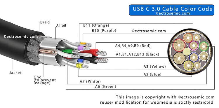
There are (4 Red, Green, Black, Green+ 1 Shield) Cables connected on each of the ends and shielding is done with conducting mesh grounded at both ends to reduce external RF interference.
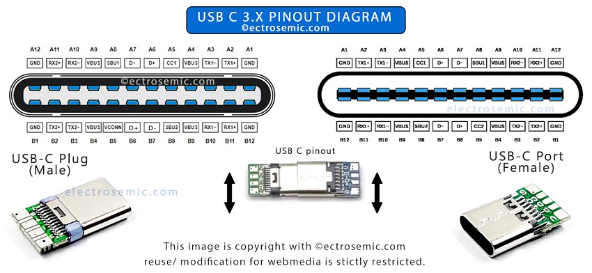
As seen from Type C end, it required 5 or 6 pin utilization:
R1 (CC1) (between A5 & Vcc) (Current Control)
Cp 10uf (optional but recommended) (between Gnd & Vcc)
On the other hand, as seen from Type A end, it takes uses 4 pins:
Vcc, D+, D-, Gnd
Also check, USB C Pinout diagram
When device is plugged in using Otg, Vcc (power) signal is used to determine whether device is connected or not.
For Signal transmission:
Pins used for Data Signal are A6 & A7 at the Port 1 and Pin no.3 & Pin No. 2 at Port 2 Type A Female using some color coded copper insulated wires. These data lines are called differential data lines as one sends plus the other receives the data simultaneously.
-> So, Pin A6 is connected to Pin 3 (D+) via Green cable
-> Pin A7 is connected to Pin 2 (D-) via White cable

For Power transmission and handling:
-The Pin no A4, B4, A9, B9, of USB-C port is grounded at both end which is connected via a Black cable Pin no.4 ground terminal of Port 2 (USB A).
-Capacitor Cp is connected in parallel to power and ground at Port 1 type C terminal. This capacitor is recommended but optional. Not shown in schematic image above.
-The combined Pin no A1 B1 A12 B12, of USB-C port is connected via a Red cable to Pin 1 of Port 2 (USB A).
-R1 is used to determine the current carrying capability or required current to the device. It is a resistor of value 5.1k Ohm or 5.6k Ohm connected between (A5) CC pin and (combined A1 B1 A12 B12) Vcc pins.

