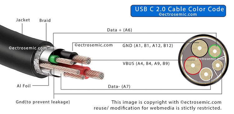
This piece of information is talking about the internal cable diagram displaying the USB C color code for the all the current generation of USB-C cables. It exhibits all the external color schemes that the Usb cable industries are using for identifying and differentiate the functional cable core from each other. In manufacturing process, this USB C wire color code comes to convenience in handling while soldering to the USB connector.
USB C cable color code for USB 2.0 Communication
In the standard USB 2.0 Type-C cable, the transmission (Tx+/ D+) and reception (Rx-/ D-) lines are important for USB 2.0 communication. Here’s the typical color coding:

Below information showing standard Type C Charger wire color code:
| Conductor Color | Pins At Port | Signal Name |
|---|---|---|
| BLACK | A1,B1,A12,B12 | GND |
| GREEN | A6 | Dp1/ Data+ |
| WHITE | A7 | Dn1/ Data- |
| RED | A4,B4,A9,B9 | VBUS |
| Shield | Gnd |
When we did the cross-section of USB C 2.0 we got above color scheme:
+5V power (Red wire), data paths (White for device-to-host, Green for host-to-device), and grounding (Black wire). Pin A5 remains unconnected and or reserved for configuration with a specified resistance for power negotiations with host device. This standardized color scheme ensures cable manufacturing/ identification reliably throughout the industry.
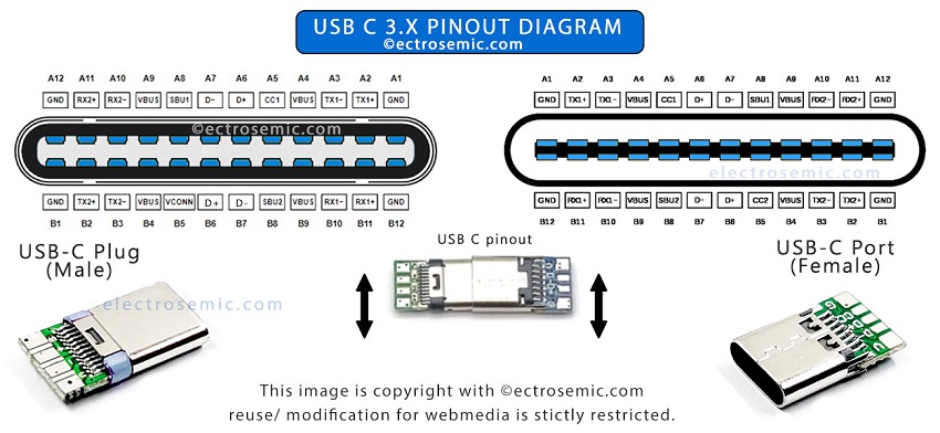
If you are into DIY project you might like this in detail USB type C pin layout diagram to deal with wiring.
USB Type C cable color code for USB 3.0, 3.1, 3.2 Communication
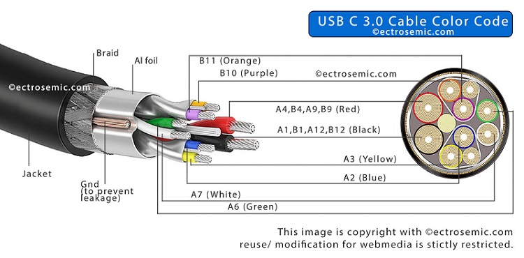
For latest fully functional USB Type-C ports or cable, more of the cable cores are implemented which are important elements for high-speed USB 3.0, 3.1 & 3.2 communication. Here’s the typical USB c wire color code:

^ Gnd (to prevent leakage) – This is conducting cable making contact with the Aluminum foil covering all the main cables, and is used to stop radiation or interference of signals from the adjacent cables.
Also, each pair of data signals are also layered with such arrangement as shown in the above image. As the USB data transfer occurs at very high frequency, thus there is a change of signal interference that may cause data leakage or data loss in the way.
^Braid and jacket is used to prevent any physical damage to internal cables by providing supporting strength.
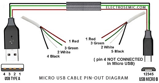
For in-depth wiring from one port to other port of USB cable, please Visit this USB C wiring diagram post. (download detail USB C wiring diagram)
Below table showing standard USB Type C wiring color code:
| Conductor Color | Pins At Port | Signal Name |
|---|---|---|
| RED | A4,B4,A9,B9 | VBUS |
| WHITE | A7 | Dn1/ D- |
| GREEN | A6 | Dp1/ D+ |
| BLACK | A1,B1,A12,B12 | GND |
| BLUE | A3 | TX1- |
| YELLOW | A2 | TX1+ |
| PURPLE | B10 | RX1- |
| Copper | GND | GND |
| ORANGE | B11 | RX1+ |
Common Misconceptions about charger cable color code
-> All blue ports are USB 3.0 or above or that color coding always follows the same standard is false. Means Blue color USB could be low speed usb 2.0 to disguise as high speed usb.
-> There is a belief that all USB-C ports offer the highest speeds and best performance. No, it doesn’t. While USB-C is a versatile connector type that can support various older or newer USB version, the device /cable supporting version determines the data transfer speed.
-> If you want to check the port / cable capability then, you can take help of utility software or third-party diagnostic tools that can provide detailed information about device USB ports and their capabilities.
-> You might be interested in USB C to 3.5mm Aux converter wiring connection diagram.

