From outside USB-C might be looking sleek & simple but behind the sleek exterior of the USB-C connector, there lies multiple core of wires having different role to take place in USB communication, their roles are simple or complex depending on the protocol that is being used for host device connections.
See Engineers, DIY enthusiasts, or technical nerd, clear understanding of the USB-C wiring diagram is somewhat needed, whether it is for designing USB device power supply/charging, tweaking projects, analyzing circuit functionality, or repairing devices.
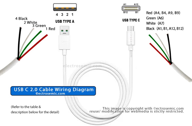
Detailed USB C cable wiring Diagram and connections:
For common USB-C which is 2.0 connectivity at maximum of 430Mbps.
This can also be seen as USB C charging cable wiring diagram and is useful in DIY projects where we may need to connect a power supply to a circuit using USB cable.
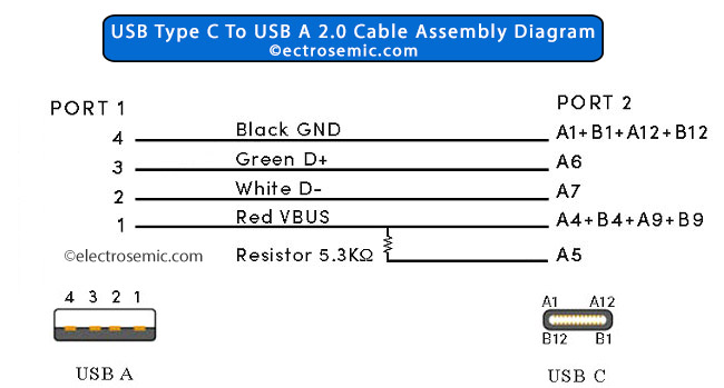
Below data shows the connection between pin-numbers on both the end and their function with their character symbol:
| At USB A port | At USB C port | Wire color | Description | Symbol |
|---|---|---|---|---|
| 1 | A4, B4, A9, B9 | Red | +5V (dc power supply) | VBUS/ VCC |
| 2 | A7 | White | Data- (data from device to host) | D- |
| 3 | A6 | Green | Data+ (data from host to device) | D+ |
| 4 | A1, B1, A12, B12 | Black | 0V (dc ground) | GND |
| NC | A5* | - | Configuration Channel 1 (VBUS through resistance Rp)^ | CC1 |
Explanation:
- The power supply is +5V DC which is standard across all devices.
But note that current capability may range from 0.2A to 2Amp or even more for fast charging. - Pin no. 1 is named, the power supply (+VDD/ VBUS) through that pin the power is supplied from source to the device, it also acts as handshake signal. The connection from pin 1 of the USB Type A male interface goes to pins A4, A9, B4, and B9 of the USB-C
- On the USB Type A male plug, pin 4 links to micro USB-C pins A1, A12, B1, and B12, which are used for ground signal (GND)
- It also includes pin 3 of the USB Type A male going to micro USB-C pin A6, and pin 2 going to pin A7.
In each port, pins 2 (D-) and 3 (D+) are designated as differential data pins, which handles the data transmission and reception based on the USB protocol. - For a comprehensive and detailed guide on USB cable color codes, please visit [USB C Cable Color Code for wire identification]. This complete guide not only provides in-depth information about the color coding standards used for various USB cables but also explains their applications and significance.
Specifically, for 2.0 USB-C cables, the color code is as follows: Red is used for pin 1, White for pin 2, Green for pin 3, and Grey or Black for pin 4. Since understanding this color code is essential for ensuring correct wiring and connectivity in USB-C applications, it also helps prevent potential issues while assembling the cable. - Note: In some cables, Pin no. A5 found not connected at the USB-C side, this removal is often a cost-cutting measure by low-end manufacturers. High-quality and more expensive cables typically ensure that A5 is utilized.
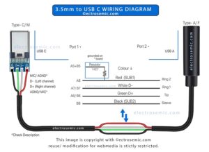
Click below image to know the 3.5mm to usb c wiring diagram:
USB C Schematic for Charger important notes:
For the charging intended function, pin A5 (CC) would be connected to the +5V supply (VBUS) through a resistor of 5.1kΩ, 5.3kΩ, or 5.6kΩ, as this resistor determines the current capability of the cable or device. Additionally, high-quality USB cables should include internal shielding and shield termination at both ends to mitigate RF interference and noise.
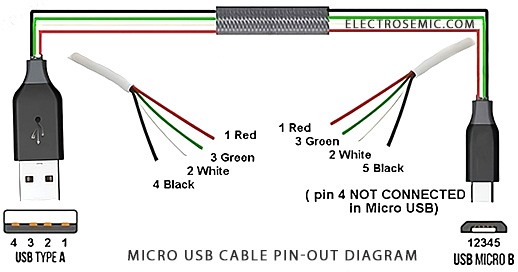
Click here for micro usb wiring, technical detail and cable wiring.