Curious about USB-C pinout, but unsure what to look for or where to start? Our detailed pinout diagram simplifies the pinout and signals functions that make USB-C so powerful and adaptable. Designed with intermediates and new learner in mind, this guide will walk you through each pin’s function, making it easier to understand and work with this USB technology.
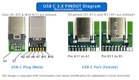
Despite the inclusive and well-designed pinout of the USB-C connector, not all of the 24 pins are actively utilized for every type of application. This act of selective pin usage is a key feature that allows USB-C to be highly adaptable and adaptable across a wide range of devices and use cases.

To make a reference, when a USB-C port is used solely for power delivery, only the power and ground pins are engaged, while the data and configuration pins remain inactive. Similarly, in applications focused on data transfer using USB 2.0 standard, super speed data pins & video output pins not to be used.
This approach ensures that the connector can efficiently handle the specific needs of different devices without the need for additional physical connectors or excessive pin configurations.
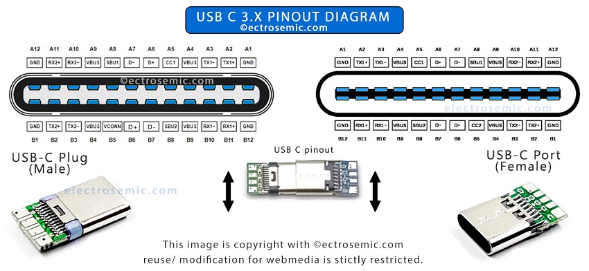
These connectors basically comes in two form factor with different intention : a male connector to plug in and a female port/ receptacle to hold plug in.
| Pin | Name | Description | Pin | Name |
|---|---|---|---|---|
| A1 | GND | DC ground (+0V) | B12 | GND |
| A2 | TX1+ | Super speed data transmit+ (host to device) | B11 | TX2+ |
| A3 | TX1- | Super speed data transmit- (device to host) | B10 | TX2- |
| A4 | VDD | DC power (+5V) | B9 | VDD |
| A5 | CC1 | Power delivery communication line | B8 | CC2 |
| A6 | D+ | Data transmit (host to device) | B7 | D+ |
| A7 | D- | Data transmit (device to host) | B6 | D- |
| A8 | SBU1 | Secondary bus | B5 | SBU2 |
| A9 | VDD | DC power (+5V) | B4 | VDD |
| A10 | RX2- | Super speed data receive- (device to host) | B3 | RX1- |
| A11 | RX2+ | Super speed data receive+ (host to device) | B2 | RX1+ |
| A12 | GND | DC ground (+0V) | B1 | GND |
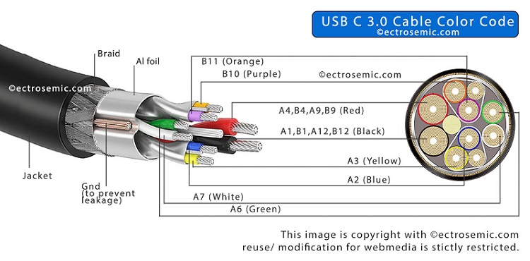
These pinout might seem confusing at first but it is assigned the USB C color code to cables for easy identifications while dealing with it.
Pinout connection of USB C full fledged:
– Pins A1 and B12 provide a 0V reference point, acting as ground connections for the circuit.
– SuperSpeed data is actively transmitted by pins A2 and B11 in the positive direction from the host to the device.
– The negative side of SuperSpeed data transmission is passively handled by pins A3 and B10, sending information from the device back to the host.
– The system is supplied with +5V DC power by pins A4 and B9.
– Active communication for power delivery is managed by pins A5 and B8.
– Positive data lines from the host to the device are actively managed by pins A6 and B7.
– Data is passively transmitted from the device to the host through the negative data lines handled by pins A7 and B6.
– Secondary bus lines for additional functionality are served by pins A8 and B5.
– Another source of +5V DC power is provided by pins A9 and B4.
– SuperSpeed data is passively received by pins A10 and B3, bringing information from the device to the host.
– SuperSpeed data is actively received by pins A11 and B2, transferring information from the host to the device.
– Stable 0V reference for reliable operation is maintained by ground connections provided by pins A12 and B1.

USB C important functional pin and their usage:
For Charging purposes:
1) VDD (Pins A4, A9, B4, B9) + GND (Pins A1, A12, B1, B12)
Usage: These pins provide the +5V DC power supply and return ground necessary for charging devices.
2) CC1 and CC2 (Pins A5, B8):
Usage: Configuration Channel pins used for detecting connection, determining cable orientation, and negotiating power delivery requirements. They help manage and communicate power delivery profiles.
3) Configuration:
As you can see in the above diagram, some Resistor or (controller IC) though the CC pins are used to for detecting connection, and negotiating power delivery requirements. For supporting dynamic charging, the controller IC is required.
Do you know?
The USB-C port designed at approximately 8.4 mm in width (~0.33 inches) and 2.6 mm in height (~0.10 inches), with a depth of around 6.65 mm (~0.10 inches). Also, the receptacle is kept at approximately same size with small difference in the order of 0.2 mm on each side.
(Some dimension varies slightly based on design and manufacturer. For more and precise detail for accurate designs it is always a good idea to refer to the datasheet provided by the manufacturer)
This compact & future-proof design of the USB-C connector allows users to plug it in either way, which is a result of symmetrical design against older USB types. With traditional USB connectors, you often had to check which way was the right orientation before plugging it in, leading to frustration when you got it wrong.
There is more to this information, check this USB C cable with schematic diagrams form manufacturers.

